Pi-AGC
A programmable Apollo Guidance Computer
Nissi Ragland (nkr33), Cameron Goddard (csg83)
14 May 2023
Demonstration Video
Introduction
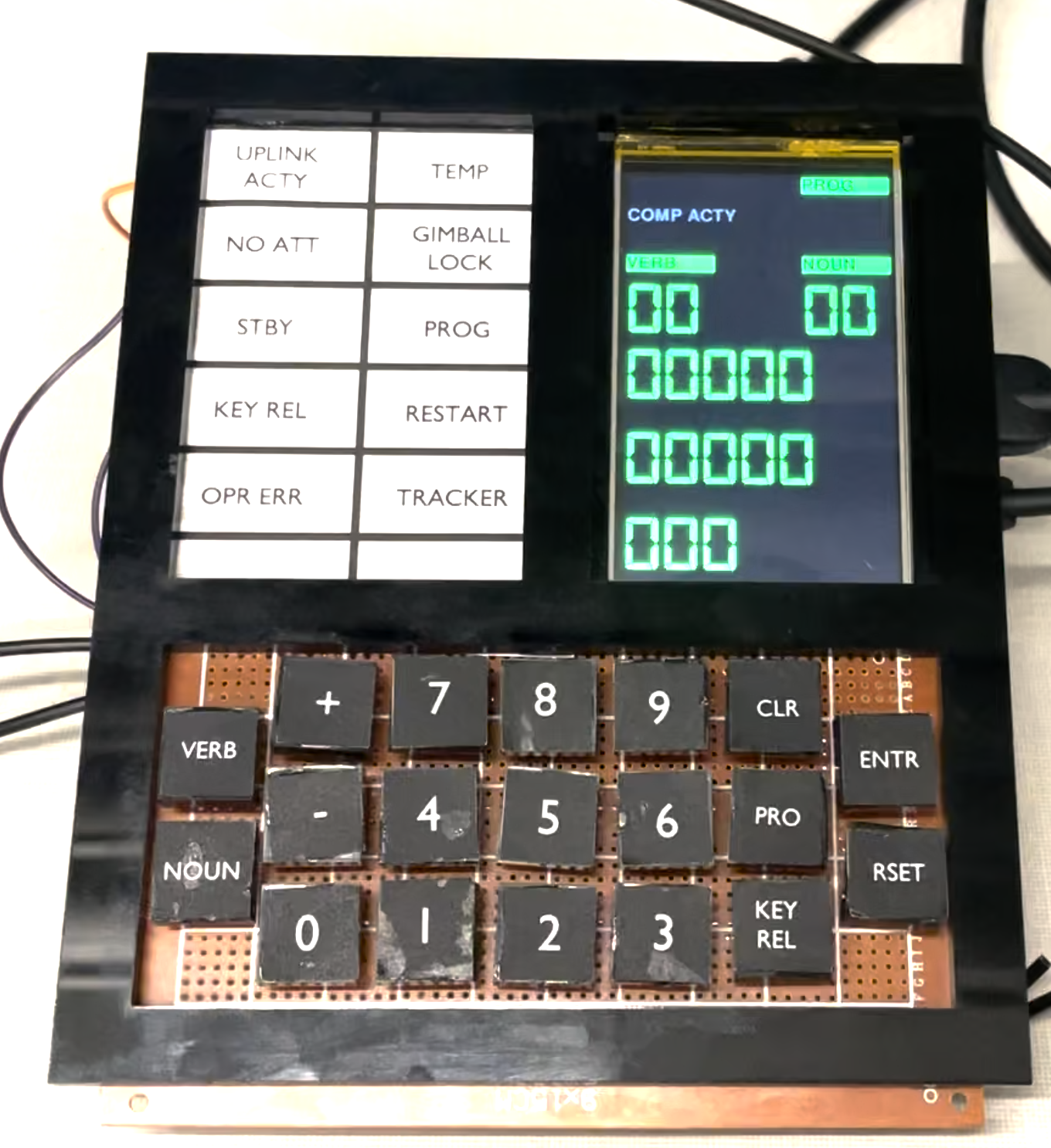
The Apollo Guidance Computer was the primary computer used by astronauts of the Apollo Program. It performed complex calculations and provided control over critical mission operations. Astronauts used the computer through an interface known as the DSKY (for DiSplay and KeYboard). For this project, we have recreated the DSKY and some of its software using Python and a Raspberry Pi 4B. Furthermore, this DSKY can run user-defined Python programs.
Project Objective:
- Create a hardware replica of the Apollo Guidance Computer DSKY
- Create authentic recreations of original AGC programs
- Make the system programmable through user-written Python programs
Design
Software
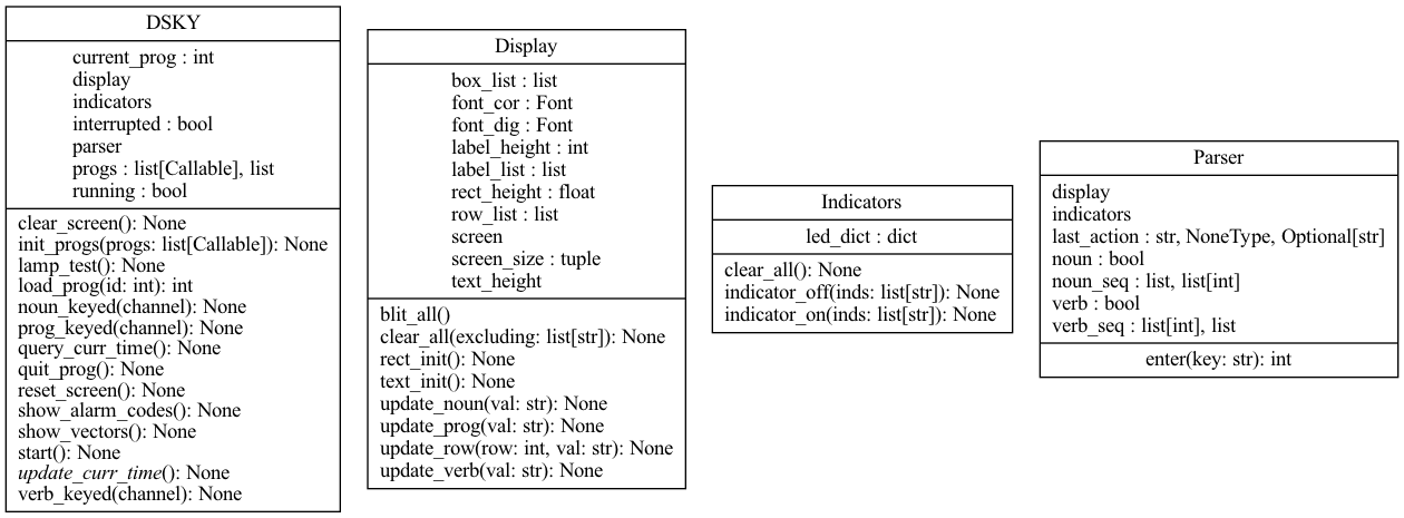
The main DSKY class manages all components of the DSKY interface and input processing. It contains two other important classes, display and indicators, which act as abstractions to the hardware and Pygame calls to their respective components. The command parser is another major component of the DSKY, and is responsible for parsing a sequence of user input keys and returning a valid program ID or throwing an error. Third-party AGC programs are simply just Python functions that follow a specific format. They are loaded in from the progs directory. The program's function is called after every input to the DSKY. It must contain two arguments: A reference to the DSKY instance, and an input string. The DSKY interface provides all the needed APIs for the program to interface with it, and the input string is whatever the last key was pressed. The input string is None if and only if the program has just loaded, so an if check for it being None can act as an init section. A program can have 3 return values; 0 for completed, -1 for an error, or -2 (or None) for a program that is still running. Below is an example of a simple echo program, which receives user input and echoes it back to the screen in the noun display.
def echo(dsky: DSKY, input: str) -> int:

    # init code
    if input == None:
        return -2

    # exit code
    if input == "return":
        return 0

    if input.isdigit():
        dsky.display.update_noun(src.util.double_str(int(input)))
To visualize the numeric displays on the original AGC, we created the display.py script which holds the class Display to create a GUI that would display all the input and output values on our HDMI display. This script relies primarily on the pygame library to achieve the original AGC-styled look.
In the initializer, display.py sets the screen along with various Rect objects that act as bounding boxes for the text. The screen is split into five different horizontal sections, each of the same height. The bottom three contain only one number, and the upper two contain two separate texts. To handle this, we further divided the upper two sections into three subsections.
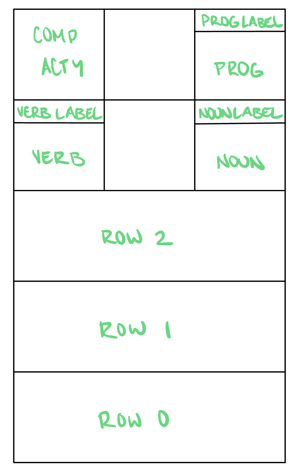
Each box in this drawing depicts a section that is defined by a Rect object. These sections hold the displayed text.
The initializer also sets the text in each of these sections to a default of zeros using the method render() on the font objects we initialized. These font objects hold the font ‘Digital 7’ for our input and output values and the font ‘Gill Sans MT’ for the labels that never change on the GUI. Finally, the initializer calls the function blit_all(), which calls the pygame method blit() on all the text attributes to overlay them onto all the Rect objects we created.
The Display class is also responsible for updating the values on the screen based on various inputs and outputs. To do this, it has the following methods:
- update_row(self, row: int, val: str): takes a row index and value as parameters and updates the text of that row to be the specified value
- update_verb(self, val: str): updates the text in the verb Rect to be the passed in value
- update_noun(self, val: str): updates the text in the noun Rect to be the passed in value
- update_prog(self, val: str): updates the text in the prog Rect to be the passed in value
- clear_all(self, excluding: list[str] = []): sets the value of every text section to be an empty string
Hardware
For the hardware component of this project, we wanted three main things: a frame, LEDs, and buttons.
Each needed to be sized carefully with respect to each other to ensure we had the correct spacing and dimensions.
For the frame, we decided to use acrylic since it is easy to laser cut into the precise dimensions we want.
We created cutouts for the HDMI display, LEDs, and buttons using the CAD software SolidWorks. Additionally, we decided to
laser cut acrylic for the keycaps that go onto the buttons. We printed black squares with the text for each key and then glued
these onto the keycaps. The keycaps were then carefully glued to the actual push button switches.
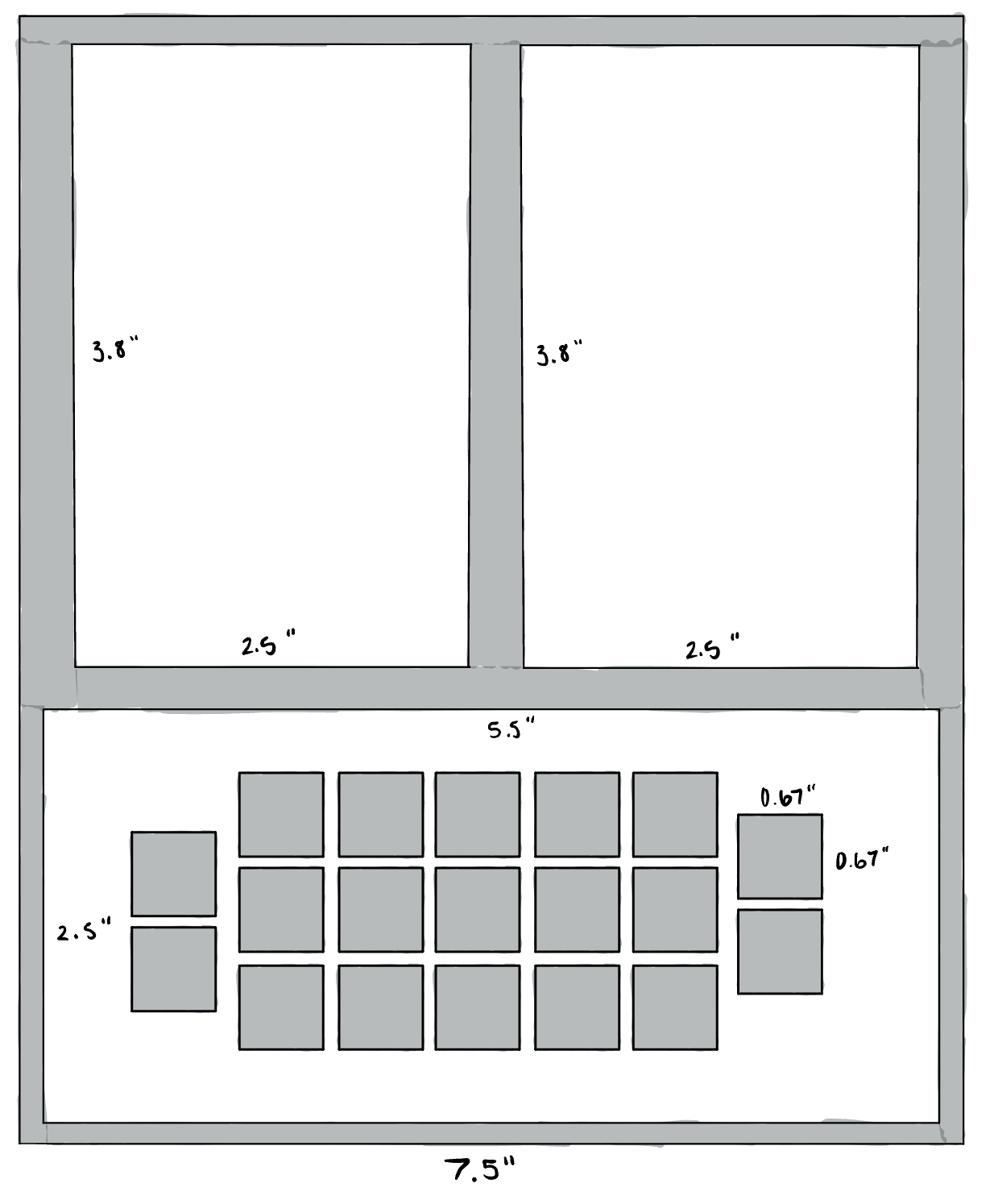
Our sketch detailing the dimensions of each component of our laser cut frame and keycaps. The grey areas represent the acrylic, while the white space is empty space that was cutout.
When we initially laser cut the frame, we added extra space around the display cutout because we wanted to create an evenly sized cutout for both the display and the indicator lights. However, this meant the HDMI display was not held in place, so we laser cut a second acrylic frame that fit the display perfectly and glued that to the back of the main frame.
Setting up the indicator lights and the keypad buttons was a very similar process. We used protoboards to lay out all of the LEDs and buttons in the precise spacing we wanted.
The ten LEDs needed to be arranged into two columns that were spaced to fit into the space between a plastic crate that we used to separate the light emitted from each LED. We then placed a paper we printed with each indicator label over the plastic crate, which was glued to the protoboard, to mimic the indicator setup on the original AGC. This entire setup was glued behind the acrylic frame in the top left cutout.
The buttons were arranged in the same way as the keypad on the original AGC. We needed to account for the size of the keycaps when placing all the buttons on the protoboard, so we carefully measured out the necessary distances between each button. As stated earlier, we completed the appearance of these buttons by gluing acrylic squares onto the tops of each push button and glued a black paper square with the correct label onto the acrylic squares. This completed the look of our keypad.
The more difficult part of the LED and button setup was the wiring. Each LED and button required its own wire to connect to the GPIO pins on the Raspberry Pi. We were able to simplify the wiring by creating a common ground for all the LEDs and for all the buttons.
For the LEDs, we soldered a resistor to the negative terminal of each LED and then soldered a path that connected all the resistors to the wire going to ground. We then connected the positive terminals of the LEDs to a jumper wire that went to a GPIO pin on the Raspberry Pi. During this process, we learned that different LED colors can have different voltage drops, meaning they require different resistance values when they are using the same power draw. We found that the blue and green LEDs needed about 50 Ohm resistors, and the red and yellow LEDs needed about 130 Ohm resistors. Using the resistors we had, we found the closest resistors we could get to those numbers and soldered them to their respective LEDs.
The buttons were more straightforward since they did not require any resistors. All we needed to do was solder one end of the push buttons to a jumper wire that connected to the GPIO pins on the Raspberry Pi and the other end to a path going to a common ground. One thing that we had to pay close attention to, however, was the orientation of the buttons. These push buttons have four prongs protruding from them. Using a multimeter, we found that these four prongs are paired in two sets of two prongs. The paired prongs are always connected to each other, but once the button is pressed, the two sets of prongs connect together, allowing current flow. This meant we had to be cautious while orienting the push buttons since we needed to ensure that we were soldering the GPIO connection to a different pair of prongs than the ground connection.
With the LED and button setup completely soldered onto the protoboards, all we had to do was glue the protoboards to their respective cutouts on the acrylic frame. Once that was complete, we had our hardware designed the way we planned.
Testing
Software
The most important software tests revolved around testing command parsing and program loading, and involved making small changes and running the program multiple times. To avoid having to run it on the Raspberry Pi every time, we developed an alternative interface for the DSKY using a normal keyboard instead of the keypad. This sped up development time substantially. Our code is able to detect when it’s running on a Raspberry Pi vs. a normal computer by checking whether it is able to import the RPi.GPIO library. If the import fails, all hardware calls will be ignored, and keyboard input will be allowed as the only interface with the DSKY.
Hardware
We created a few useful unit tests in the tests directory over the course of the development of this project. For testing buttons, we initialized every GPIO button and printed out their GPIO number via callback functions. This script helped us catch when some buttons would fail or were wired incorrectly. We wrote a similar test for our LEDs to test that each LED was able to blink.
Results and Conclusions
For our demonstration, our software performed as expected. The GUI displayed on the HDMI monitor, the LED and button behavior
was as expected, and all our programs ran correctly. However, some hardware components did not work as intended. We had a couple buttons stop working on the day of our demonstration,
and from examining the soldering and testing with a multimeter, we were unable to discover what went wrong with those buttons. To work around this, we used an external keyboard
as a backup and disabled all button inputs except those of the VERB and NOUN key.
We accomplished our goal from our project proposal of emulating the original AGC in terms of hardware design and being able to run actual commands that existed on it.
Originally, we planned to use our AGC model to simulate a lunar landing, but due to the complexity of simulation and the limited time we had, we pivoted from this idea
to instead making our AGC a completely programmable computer. We created a few Python programs that could run on our AGC, demonstrating its ability to run various types
of programs. While we had to alter our original idea, we still were able to accomplish adding an interesting change to the original AGC design to make our Pi-AGC a
unique machine.
Future Work
Future work on this project could go in all sorts of different directions. Time could be spent on recreating more commands from the original AGC. A whole mission could be simulated from start to end to provide even more useful sensing and actuation commands. The system of loading programs could be further expanded so that you could run programs that were loaded into the computer after it has booted. One idea for this is to read program files from a flash drive that is plugged into the Pi.
Work Distribution
Cornell Rocketry Team

Nissi Ragland
nkr33@cornell.edu
Built the hardware and GUI.

Cameron Goddard
csg83@cornell.edu
Designed the software architecture.
Parts List
- Raspberry Pi 4B - $35.00
- 4-inch HDMI LCD display - $38.99
- Push button switches - $9.90
- LEDs, Resistors, and Wires - Provided in lab
Total: $83.89
References
The Virtual AGC ProjectMoonjs: An Online Apollo Guidance Computer Simulator
Pygame Docs
R-Pi GPIO Document
Code Appendix
Code is available on GitHub